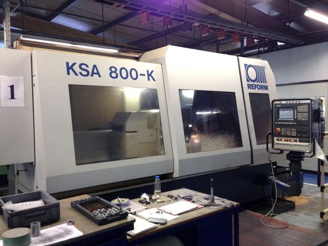
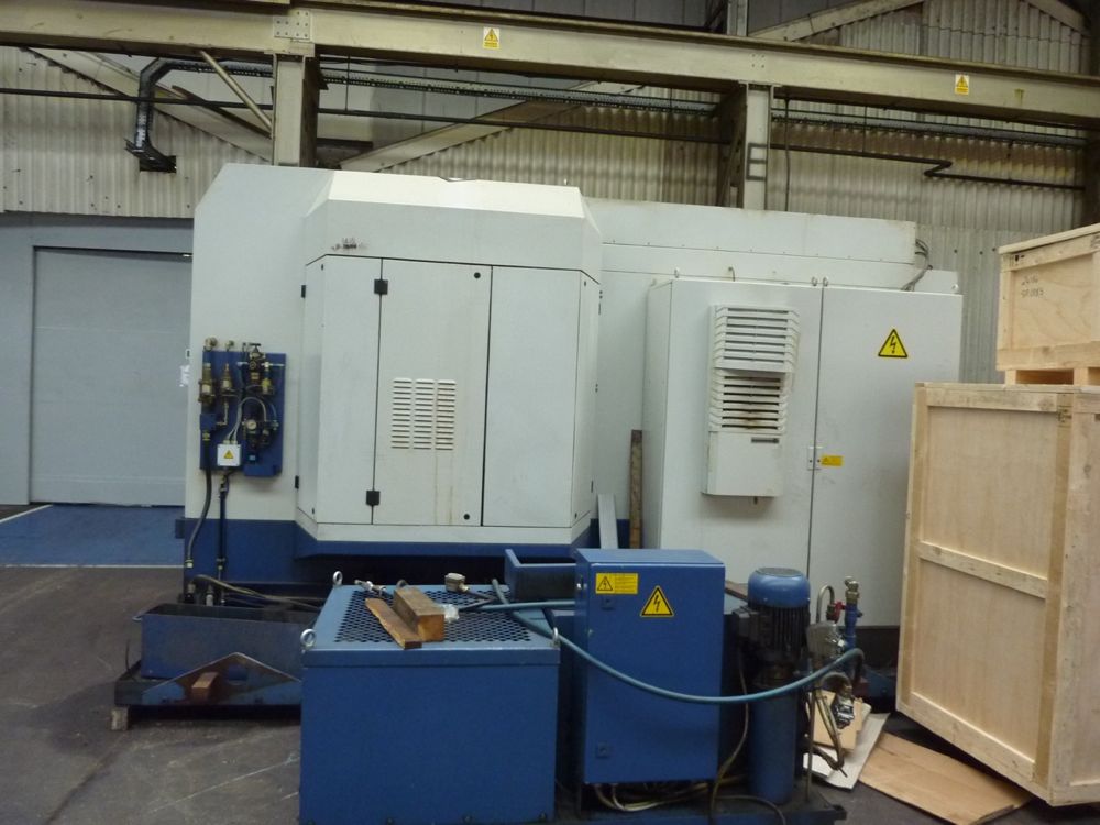
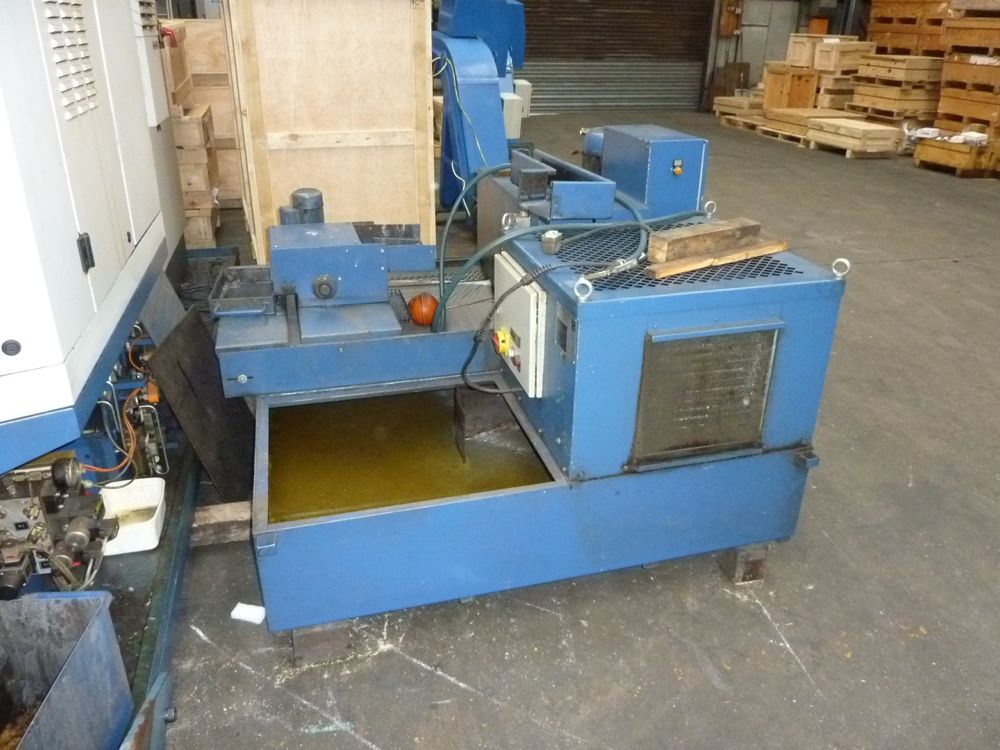
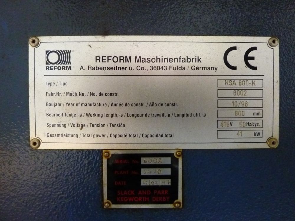
Lot 1 - Reform KSA 800-K CNC Gear and Spline grinding machine
Description:
Reform KSA 800-K CNC Gear and Spline grinding machine.
Bought new in 1996.
Technical Data:
Centre Height: 200mm
Distance Between Centers: 800mm
Grinding Length (wheel diameter dependant)
Dia 250 - 650mm
Dia 150 - 700mm
Max Grinding Diameter: 250mm
Min Grinding Diameter: 10mm
Table Speed Max 30m/min
Max Grinding Wheel Diameter:250mm
Min Grinding Wheel Diameter: 40mm
Grinding Drive Motor: Approx. 5.5 kW
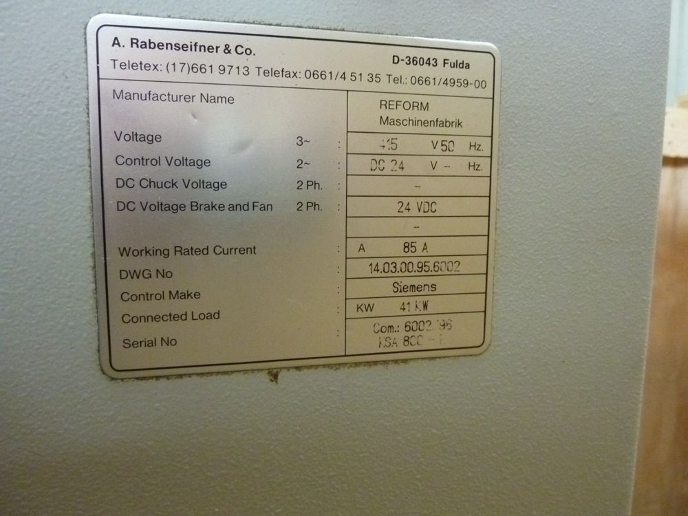
Voltage: 380 Volts
Phase: 3 Ph
Frequancy : 50 Hz
Total Power Consumption: 24 KVA
Approx. M/C Weight: 5100 Kg
Dimensions:
length: 3550mm
Width: 1900mm
Height: 2200mm
Grinding Wheel Profile / Trueing Attachment - 3 axis NC controled
Cooling System
Paper Band filter System
Indexing Attachment
Mounting Cone
Divisions (odd divisions possible): 1-999
Max Workpeice weight: 240 Kg
Machine Description (Taken from Machine manual):
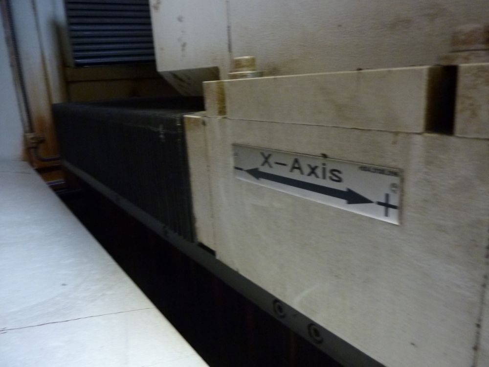
Table drive (x-axis)
The machine table is oscillated throughpreloaded play free ball-thread drive. The drive is effected by a nut drivethrough 3-phase servomotor and tooth belt. The support speed is in the range of1-30 u/mm steplessly variable. Exchanging and tightening of the tooth belt iseffected by means of an adjustable screw. The position of the machine table is registeredby a rotary encoder positioned on the spindle or by a linear gauge positioned onthe machine table respectively machine bed.
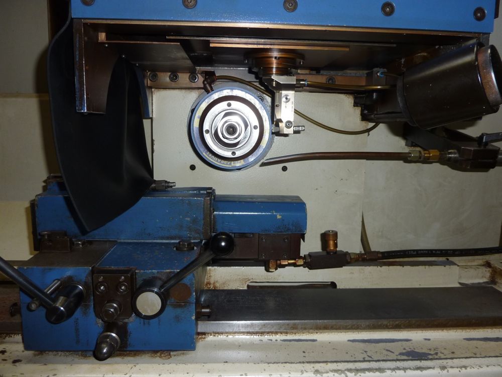
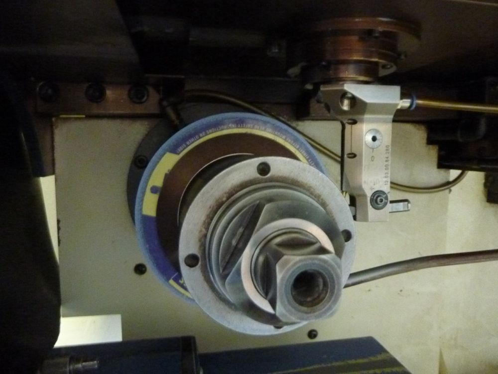
Grinding spindle
The grinding spindle is mounted on acylindrical bore of the grinding spindle carriage and is replaceable. A 3-phaseservomotor serves as drive, which is connected through belts with the beltpulley of the grinding spindle. The tightening of the grinding spindle bearing resultthrough labyrinth sealing’s.
Constant Cutting Speed
With the controllable 3-phase-servo-motor it is possible to keep theperipherical speed of the grinding wheel constant, although the diameter of thegrinding wheel becomes continuously smaller due to the dressing. The control ofthe speeds is effected through a computer control. As the peripherical speed ofthe grinding wheel depends on the grinding wheel radius and the size of thechosen grinding spindles these values have subsequently to be transmitted tothe control in form of parameters.
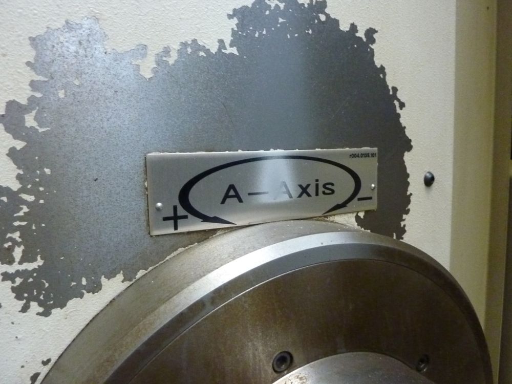
NC- Indexing device
The indexing device is equipped with anelectro-hydraulical clamping. After each indexing the spindle is clamped in theplaced position, so that the angle position is not influenced. The nextindexing only results, after the clamping has released the indexing spindle.The worm gear - made out of special bronze cast, or hardened groundcasehardening steel - is radially adjustable, in order to keep the flank playas low as possible. A possible wearing of the drive can thus be compensatedeven after a few years.
The NC-indexing device allows I up to999 indexings, whereby random indexings are possible, if other specialindexings requests this, The indexing-process results optionally after eachstroke or double stroke of the machine table, if the grinding wheel is out ofthe range of the workpiece profile.
The drive of the indexing device iseffected by a servo-motor, which drives through a timing belt the worm gearing.Timing belts have to be exchanged in time to keep the precision of the device.The indexing device is equipped with a direct measuring system. A proximityswitch exists in order to find the reference point.
The indexing spindle is short-beared inhigh-precision-cone-roll-bearings, which are preclamped and installed so that abearing play can not occur when the temperature rises.
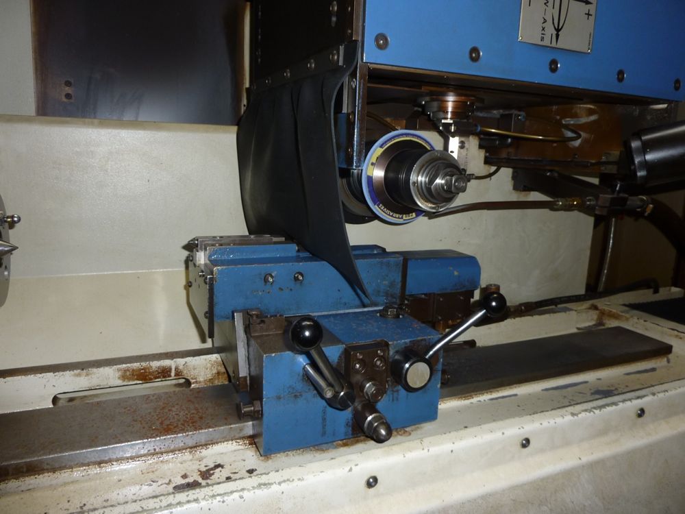
Hydraulic tailstock
The tailstock can be moved in its guideon the table. It must be adjusted to accord with workpiece length and locked inposition. The tailstock center can be hydraulically retracted using afoot-switch on the bed in order to release the workpiece. The foot-switch isactive when the table is in the “Change Workpiece” position and the tailstockis selected on the operating panel. The tailstock centre is loaded by a sprinqduring clamping of the workpiece. Clamping of the tailstock centre is performedmanually.
Steady rests
For the support of long workpìeces youcan mount steady rests on the table guiding. With the steady rests you cansupport in the spline profile or in the cylindrical part of the spline shaft.
For the support of internal broachesother steady rests can be mounted on the table guiding. The workpiece holdersof the steady rests are replaceable for different diameter ranges. Theadjustment of the ram is 30 mm. The workpiece holders have to be accornodatecito different profiles according to the holder conditions. The tilt-up-processof the internal broaches is avoided through a wire, which is torn around thebearing after the internal broach is clamped. To tighten the wire, a toggledevice is used.
For the reinforcement of spline shaftssteady rests with replaceable bearing boxes which are synchronized to the samerange of diameter are installed.
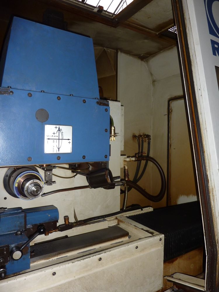
NC-dresser
The dresser serves for the profilingand dressing of grinding wheels with a one-grain- diamond. One at the U- andW-axis traversable cross-carriage clamps the working plane 120 x 120 mm. Thecross carriage bears the diamond-holder which is orientable around theB-axis, whereby the B-axis stands vertical on the working plane.
The cross carriage, which is supportedby the grey cast iron box has angular needle guidings for U- and W-axis.Angular-contact ball bearings have been applied for the B-axis. Direct currentmotors drive each axis individually in connection with a timing belt. U- andW-axis are seized through a linear measuring system, the B-axis is controlledthrough angle encoder.
The NC-dresser is one of the mostcomplex assemblies of the machine. We stongly dissuade from the intervention ata breakdown without having contacted in advance the producer. Should anyproblems in this connection arise, there is the possibility to call ourafter-sales-service.
Guiding of the grinding slide
The large guiding width and -length aswell as the adjustable wedges serve for exact guiding of the grinding wheel.Due to anti friction guidings with needle roller cages between the hardenedguideways a very precise and smooth adjustment of the grinding slide isprovided.
The guiding is covered against grindingdust with accordeon way covers and strippers.
Grinding slide adjustment
During the fully automatic operationprocess various preselectable donwfeed values are put out as control signalsfor the downfeed motor. A nearly playfree spur gearing on the pre-clarnpedcirculating roller nut in connection with a precise and smooth guiding of the grindingslide guaranties for exact downfeed of the grinding wheel.
Table guiding
The high guiding precision of thesupport is effected by the following construction
characteristics:
V-prism with great plane under the center of gravity of the support andlateral flat guiding. Long guiding distance at the table
The indexing device and the tail stock in the position for accepting thelongest span The indexing device and the tail stock in the position for accepting thelongest workpiece are positioned within the range of table guiding profile.
Uninterruptable lubrication supply over the whole guiding.
Table drive
The machine table drive is effected by ballscrew drive, tooth belt and three phase servo motor. The table speed can beadjusted steplessly up to 30 m/min. The position of the machine table istcontrolled by means of a linear gauge or rotary encoder.
The thread roller screw drive isequipped with ground spindle thread. The satellite rollers are constantlygripping into the spindle and nut thread. The rollers do not effect an axial movementin the nuts, it is not necessary return them.
Driving flange
The driving flanges are bolted onto theindexing head in accordance with the diameter range of the workpiece. The flangeshave a slot in which the ballhead engages and thus ensures that the workpieceis driven at exactly the required angle.
Driving flanges available in thefollowing ranges:
Dia. 10mm todia. 32 mm
Dia. 60 mm to dia. 150 mm
Driver
The driver are clamped onto a suitablediameter of tolerable contentricity. They engage in the slot of the drivingflange on the drividing attachment with on respectively two ballheads.
The clamping range of the driver hasfour diameter size.
Dia. 10 mm to dia. 31 mm Dia. 31 mm todia. 60 mm
Dia. 60 mm to dia. 105 mm Dia,105 mm todia. 150 mm
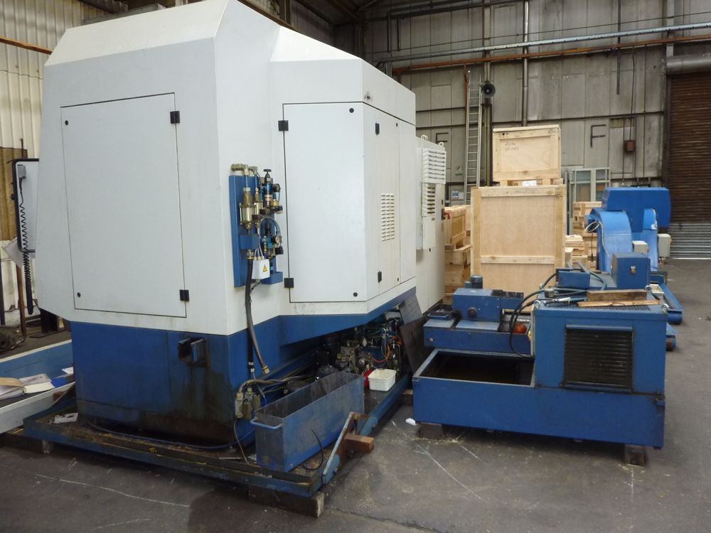
Machine Condition,
The machine has been used vitrually 74 hours per week since late 1996 when it was installed. It has had services from the OEM nearly every two years.
Export Information
Please note: If you are successful in purchasing an item and wish to export it from the UK, a charge of £75.00 will be automatically added to your invoice to cover preparation of the goods and completion of the required UK export customs declarations. This process has been a mandatory UK export requirement since 1 January 2021.
All invoices are issued on an Incoterms FCA basis.
Exports outside the EU may require an export licence. Where applicable, a further charge of £250.00 will be automatically added to your invoice. Please also note that, while an export licence is being processed, the purchaser is responsible for placing into storage until the licence is issued.
* Please note all dimensions stated are approximate, however the accuracy cannot be guaranteed and should be verified by the bidder before bidding.


Bid information
Time remaining
06 Mar 2014 15:00:00 GMT